Search This Blog

Monday, December 26, 2011

Frame-Relay Switch and Bridge


Here is the following scenario:

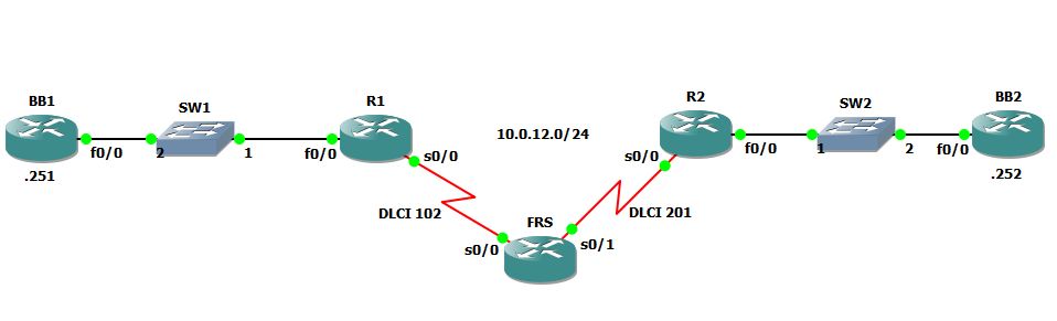
First we will have to configure FRS, which is 2961 IOS router, to a frame-relay switch.
The logic is quite simple with 3 simple steps:
      1. Enable frame-relay switching using the command: frame-relay switching
      2. Configure each of the interfaces with frame-relay configuration:
interface Serial0/0
 no ip address
 encapsulation frame-relay
 clock rate 128000
 frame-relay intf-type dce
!
interface Serial0/1
 no ip address
 encapsulation frame-relay
 clock rate 128000
 frame-relay intf-type dce

No IP address, encapsulation frame-relay, clock rate and most important interface type which should be, on the service provider side, set to DCE (the default is DTE which should be on the CPE side).
     3.        Bond the two interfaces using the connect command:
connect R1_R2 serial 0/0 102 serial 0/1 201

Now let’s configure R1 and R2 CPE routers for frame-relay connection.
R1 Configuration:
interface Serial0/0
 ip address 10.0.12.1 255.255.255.0
 encapsulation frame-relay
 clock rate 128000
 frame-relay map ip 10.0.12.2 102 broadcast
 frame-relay interface-dlci 102
 no frame-relay inverse-arp
end

R2 Configuration:
interface Serial0/0
 ip address 10.0.12.2 255.255.255.0
 encapsulation frame-relay
 clock rate 128000
 frame-relay map ip 10.0.12.1 201 broadcast
 frame-relay interface-dlci 201
 no frame-relay inverse-arp
end

Note that due to the fact that we are configuring on the physical interface, which connected to frame-relay cloud, we have to configure a static map between R1 and R2 or enable inverse-arp.
While showing frame-relay mapping:
R2#sh frame-relay map
Serial0/0 (up): ip 10.0.12.1 dlci 201(0xC9,0x3090), static,
              broadcast,
              CISCO, status defined, active
The static statement indicates frame-relay static map where if we had enable inverse-arp we will see the dynamic statement as follows:
R2#sh frame-relay map
Serial0/0 (up): ip 10.0.12.1 dlci 201(0xC9,0x3090), dynamic,
              broadcast,, status defined, active
Else we can configure logical interface with point-to-point configuration:
R1 Configuration:
interface Serial0/0
 no ip address
 encapsulation frame-relay
 clock rate 128000
!
interface Serial0/0.12 point-to-point
 ip address 10.0.12.1 255.255.255.0
 snmp trap link-status
 frame-relay interface-dlci 102  

R2 Configuration:
interface Serial0/0
 no ip address
 encapsulation frame-relay
 clock rate 128000
!
interface Serial0/0.21 point-to-point
 ip address 10.0.12.2 255.255.255.0
 snmp trap link-status
 frame-relay interface-dlci 201

Show frame-relay map indicates point-to-point network type:
R2#sh frame-relay map
Serial0/0.21 (up): point-to-point dlci, dlci 201(0xC9,0x3090), broadcast
          status defined, active
Now let’s assume that we want to bridge over the frame-relay network between BB1 and BB2, which reside on the same segment.
First I cleared R1 and R2 serial interfaces using the command: default interface serial 0/0
R1 bridging configuration:
bridge 1 protocol ieee
!
bridge irb
!
interface FastEthernet0/0
 no ip address
 duplex auto
 speed auto
 bridge-group 1
!
interface Serial0/0
 no ip address
 encapsulation frame-relay
 clock rate 128000
 frame-relay map bridge 102 broadcast
 bridge-group 1

R2 bridging configuration:
bridge 1 protocol ieee
!
bridge irb
!
interface FastEthernet0/0
 no ip address
 duplex auto
 speed auto
 bridge-group 1
!
interface Serial0/0
 no ip address
 encapsulation frame-relay
 clock rate 128000
 frame-relay map bridge 201 broadcast
 bridge-group 1

Now BB1 can ping BB2:
BB1#ping 10.0.12.252
Type escape sequence to abort.
Sending 5, 100-byte ICMP Echos to 10.0.12.252, timeout is 2 seconds:
!!!!!
Success rate is 100 percent (5/5), round-trip min/avg/max = 20/54/100 ms

Thursday, December 22, 2011

BGP Capabilities Advertisment

While setting up an IPv6 lab i have encounter a strange output from one of the routers, although the BGP peer has been setup  and they have exchange prefixes, R4 show ip bgp summary output shows the following:


Note the (NoNeg) under the state/PfxRcd section.

Looking on R1 configuration i have noticed that no neighbor 2001::4 active has been configured under IPv4 address family and that's despite the fact that I'm not using an IPv4 at all.


Doing some packet capture pointed to the reason of BGP capabilities advertisement, while the neighbor is not activate, in IPv4 and IPv6, he is not advertising his capabilities to his peer neighbor:


changing the neighbor to activate has solved this issue:


note that this happens only with IPv4 while IPv6 is running normal:


Logging Debugging output to Syslog server

Here is small note configuration for configuring Cisco router to send debugging level information to Syslog server:

Router(config)#logging host 192.168.10.2
Router(config)#logging trap 7
Router(config)#logging on

Where 192.168.10.2 is my Syslog server and trap 7 is debugging level.

Wednesday, December 21, 2011

SecureCRT Copy tip


While working with SecureCRT, or with any other terminal application, the need to copy information is required.
Dragging the cursor, on the terminal, works in a way which copies line by line instead of the required information only,
For example let’s say we want to copy only the IP addresses in the show ip interface brief output:


As you can see it will copy all the lines including the interface name, IP, status, protocol and etc.

In order to copy only the IP addresses, hold down the ALT key while dragging the cursor over the IP addresses and….that’s it!


now i can paste these IP's directly to a TCL script for example without the need to parsing the copied information.

Tuesday, December 13, 2011

Another RIPv2 LAB


Another RIPv2 LAB


Here is the following network scenario:
 R1 is advertising 4 networks: 192.168.10.x to 192.168.40.x, on each task I have configured different way to control and manipulate the routes using distance, offset-list and distribute-list.

First task was to advertise network 192.168.20.0/24 to R5 through R2 only, this has achieved through distribute-list configured on R5
An extended access-list has been configured:
access-list 100 permit ip host 10.0.25.2 192.168.20.0 0.0.0.0
access-list 100 deny   ip any host 192.168.20.0
access-list 100 permit ip any any

The first line point the source of the advertisement (10.0.25.2) and the route prefix (192.168.20.0/24), second line deny this network from any other source and the third line allow all other advertisements.

Then configure this ACL using distribute-list under router configuration:
Router rip
 distribute-list 100 in

The second task was to advertise network 192.168.30.0/24 through R3 to R5 using offset-list on R2 and R4.

Configure standard ACL which will recognize this network:
access-list 30 permit 192.168.30.0

And then, under the router configuration, configure offset-list, toward the interface to R5, which will rise up the metric (hop count in RIP) over 16 which is eventually unreachable:
offset-list 30 out 15 FastEthernet0/1

Third task was to allow R5 to accept network 192.168.10.0/24 from R3 and, in case of failure, from R4.

A standard ACL for recognize this network:
access-list 10 permit 192.168.10.0

And then configure distance under the router configuration:
distance 255 10.0.25.2 0.0.0.0 10
distance 150 10.0.45.4 0.0.0.0 10

Distance change the AD locally on R5, while the first line sets AD to network 192.168.10.0/24 received from R2 to 255 – which is unknown, the second sets the same from R4 to AD of 150 while R3 remain with RIP default AD of 120.


Saturday, December 10, 2011

RIPv2 Default route


RIP use the command default-information originate in order to advertise default route to his neighbors, while there is another feature which allows us to do conditional route advertise.

For example, following the network diagram on the previous post,  I have configured network 172.16.40.0/24 in access-list 40:
access-list 40 permit 172.16.40.0 0.0.0.255

Then configure route-map to match that network:
route-map NET-40 permit 10
 match ip address 40

And finally configure default-route under RIP router:
router rip
 version 2
 network 10.0.0.0
 network 192.168.10.0
 network 192.168.20.0
 network 192.168.30.0
 network 192.168.40.0
 network 192.168.50.0
 default-information originate route-map NET-40
 distribute-list 111 in
 distance 90 10.0.15.5 0.0.0.0 50
 no auto-summary

The result - R1 is advertising default route to his neighbors as long as network 172.16.40.0/24 is exist in his routing table:
R3#show ip route
Codes: C - connected, S - static, R - RIP, M - mobile, B - BGP
       D - EIGRP, EX - EIGRP external, O - OSPF, IA - OSPF inter area
       N1 - OSPF NSSA external type 1, N2 - OSPF NSSA external type 2
       E1 - OSPF external type 1, E2 - OSPF external type 2
       i - IS-IS, su - IS-IS summary, L1 - IS-IS level-1, L2 - IS-IS level-2
       ia - IS-IS inter area, * - candidate default, U - per-user static route
       o - ODR, P - periodic downloaded static route

Gateway of last resort is 10.0.123.1 to network 0.0.0.0

R    192.168.30.0/24 [120/1] via 10.0.123.1, 00:00:02, FastEthernet0/0
R    192.168.10.0/24 [120/1] via 10.0.123.1, 00:00:02, FastEthernet0/0
R    192.168.40.0/24 [120/1] via 10.0.123.1, 00:00:02, FastEthernet0/0
     172.16.0.0/24 is subnetted, 5 subnets
R       172.16.50.0 [120/1] via 10.0.34.4, 00:00:14, FastEthernet0/1
R       172.16.40.0 [120/1] via 10.0.34.4, 00:00:14, FastEthernet0/1
R       172.16.30.0 [120/1] via 10.0.34.4, 00:00:14, FastEthernet0/1
R       172.16.20.0 [120/1] via 10.0.34.4, 00:00:16, FastEthernet0/1
R       172.16.10.0 [120/1] via 10.0.34.4, 00:00:16, FastEthernet0/1
R    192.168.20.0/24 [120/1] via 10.0.123.1, 00:00:03, FastEthernet0/0
     10.0.0.0/24 is subnetted, 5 subnets
R       10.0.15.0 [120/1] via 10.0.123.1, 00:00:03, FastEthernet0/0
R       10.0.24.0 [120/1] via 10.0.123.2, 00:00:00, FastEthernet0/0
                  [120/1] via 10.0.34.4, 00:00:16, FastEthernet0/1
R       10.0.45.0 [120/1] via 10.0.34.4, 00:00:17, FastEthernet0/1
C       10.0.34.0 is directly connected, FastEthernet0/1
C       10.0.123.0 is directly connected, FastEthernet0/0
R    192.168.50.0/24 [120/1] via 10.0.123.1, 00:00:05, FastEthernet0/0
R*   0.0.0.0/0 [120/1] via 10.0.123.1, 00:00:05, FastEthernet0/0

Shutting down interface loopback 4 on R4 will make R1 to redraw the default route.

Friday, December 9, 2011

RIPv2 - Offset-list, distribute-list and AD

Here is the network diagram:


R4#configure terminal
Enter configuration commands, one per line.  End with CNTL/Z.
R4(config)#router rip
R4(config-router)#network 172.16.10.0
R4(config-router)#network 172.16.20.0
R4(config-router)#network 172.16.30.0
R4(config-router)#network 172.16.40.0
R4(config-router)#network 172.16.50.0


RIPv2 will summarize contiguous networks to their classful boundaries although no auto-summary is configured.


the result:
R4#show running-config | s rip
router rip
 version 2
 network 10.0.0.0
 network 172.16.0.0
 no auto-summary


Also the RIP database shows the following:
R4#show ip rip database
10.0.0.0/8    auto-summary
10.0.15.0/24
    [1] via 10.0.45.5, 00:00:20, FastEthernet1/0
10.0.24.0/24    directly connected, FastEthernet0/0
10.0.34.0/24    directly connected, FastEthernet0/1
10.0.45.0/24    directly connected, FastEthernet1/0
10.0.123.0/24
    [1] via 10.0.34.3, 00:00:13, FastEthernet0/1
    [1] via 10.0.24.2, 00:00:06, FastEthernet0/0
172.16.0.0/16    auto-summary
172.16.10.0/24    directly connected, Loopback1
172.16.20.0/24    directly connected, Loopback2
172.16.30.0/24    directly connected, Loopback3
172.16.40.0/24    directly connected, Loopback4
172.16.50.0/24    directly connected, Loopback5
192.168.10.0/24    auto-summary
192.168.10.0/24
    [2] via 10.0.45.5, 00:00:20, FastEthernet1/0
    [2] via 10.0.34.3, 00:00:13, FastEthernet0/1
    [2] via 10.0.24.2, 00:00:06, FastEthernet0/0
192.168.20.0/24    auto-summary
192.168.20.0/24
    [2] via 10.0.45.5, 00:00:20, FastEthernet1/0

<Output omitted>

So now we will use distribute-list in order to decide what and to whom we will advertise networks, for example:
R4(config)#ip access-list standard 10 
R4(config)#permit 172.16.10.0 0.0.0.255
R4(config)#permit 172.16.20.0 0.0.0.255

then add a distribute-list on router configuration, outbound interface toward R5 (Fa1/0):
router rip
 version 2
 network 10.0.0.0
 network 172.16.0.0
 distribute-list 10 out FastEthernet1/0
 no auto-summary

the result:
R5#sh ip route     
Codes: C - connected, S - static, R - RIP, M - mobile, B - BGP
       D - EIGRP, EX - EIGRP external, O - OSPF, IA - OSPF inter area
       N1 - OSPF NSSA external type 1, N2 - OSPF NSSA external type 2
       E1 - OSPF external type 1, E2 - OSPF external type 2
       i - IS-IS, su - IS-IS summary, L1 - IS-IS level-1, L2 - IS-IS level-2
       ia - IS-IS inter area, * - candidate default, U - per-user static route
       o - ODR, P - periodic downloaded static route

Gateway of last resort is not set

     172.16.0.0/24 is subnetted, 2 subnets
R       172.16.20.0 [120/1] via 10.0.45.4, 00:00:00, FastEthernet0/0
R       172.16.10.0 [120/1] via 10.0.45.4, 00:00:00, FastEthernet0/0
     10.0.0.0/24 is subnetted, 1 subnets
C       10.0.45.0 is directly connected, FastEthernet0/0

R5 will have only 172.16.10.0/24 and 172.16.20.0/24 from R4.

Now with extended ACL the things are little bit different,  first RIP will accept only numeric extended ACL's and the treatment to extended ACL is as follow:
1. The first host/network is reference as the next-hop
2. The second host/network is referene as the advertised network

For example:
R1#show ip access-lists 111
Extended IP access list 111
    10 permit ip host 10.0.123.2 172.16.10.0 0.0.0.255
    20 permit ip host 10.0.123.2 172.16.20.0 0.0.0.255
    30 permit ip host 10.0.123.3 172.16.30.0 0.0.0.255
    40 permit ip host 10.0.123.3 172.16.40.0 0.0.0.255
    50 permit ip any 172.16.50.0 0.0.0.255

this ACL instruct to receive 172.16.10.0/24 and 172.16.20.0/24 only if the next-hop is 10.0.123.2 and 172.16.30.0/24 and 172.16.40.0/24 only if the next-hop is 10.0.123.3.
Network 172.16.50.0/24 will be accepted from any source and all other RIP updates will deny.

Configuring this extended ACL as R1 inbound filter:

R1#show running-config | s rip
router rip
 version 2
 network 10.0.0.0
 network 192.168.10.0
 network 192.168.20.0
 network 192.168.30.0
 network 192.168.40.0
 network 192.168.50.0
 distribute-list 111 in
 no auto-summary

the result:
R1#show ip route rip
     172.16.0.0/24 is subnetted, 5 subnets
R       172.16.50.0 [120/7] via 10.0.123.3, 00:00:25, FastEthernet0/0
                    [120/7] via 10.0.123.2, 00:00:22, FastEthernet0/0
                    [120/7] via 10.0.15.5, 00:00:17, FastEthernet0/1
R       172.16.40.0 [120/7] via 10.0.123.3, 00:00:25, FastEthernet0/0
R       172.16.30.0 [120/7] via 10.0.123.3, 00:00:25, FastEthernet0/0
R       172.16.20.0 [120/7] via 10.0.123.2, 00:00:22, FastEthernet0/0
R       172.16.10.0 [120/7] via 10.0.123.2, 00:00:22, FastEthernet0/0

Now while RIP allows up to 16 equal-cost paths he install by default only 4, the load-balance between the paths is based on the switching method and on most routers using fast-swicthing or CEF it will use per-destination basis.

Note that network 172.16.50.0/24 is seen from both R2, R3 and R5, now let's say we want to prefer R5 as the next-hop to this network. For this case we will use offset-list.

First configure standard ACL for identify the network:
R1#show ip access-lists 50
Standard IP access list 50
    10 permit 172.16.50.0, wildcard bits 0.0.0.255

Then configure the offset-list in RIP:
R1(config)#do sh run | s rip
router rip
 version 2
 offset-list 50 in 5 FastEthernet0/0
 network 10.0.0.0
 network 192.168.10.0
 network 192.168.20.0
 network 192.168.30.0
 network 192.168.40.0
 network 192.168.50.0
 distribute-list 111 in
 no auto-summary


I have configured offset-list 50, which refer to ACL 50, with offset of 5 - hence add 5 to the metric received from interface FastEthernet 0/0 for network 172.16.50.0/24

the result:
R1#show ip route rip
     172.16.0.0/24 is subnetted, 5 subnets
R       172.16.50.0 [120/2] via 10.0.15.5, 00:00:08, FastEthernet0/1
R       172.16.40.0 [120/2] via 10.0.123.3, 00:00:12, FastEthernet0/0
R       172.16.30.0 [120/2] via 10.0.123.3, 00:00:12, FastEthernet0/0
R       172.16.20.0 [120/2] via 10.0.123.2, 00:00:14, FastEthernet0/0
R       172.16.10.0 [120/2] via 10.0.123.2, 00:00:14, FastEthernet0/0


We can also use the offset-list to add hop metric for advertised networks as well.

Another method for controlling RIP in/out routes is using the administrative-distance, note that i have removed the offset-list from the previous example:
R1(config-router)#distance 90 10.0.15.5 0.0.0.0 50

this will change the administrative distance for network 172.16.50.0/24, which defined by ACL 50, and received by source host 10.0.15.5 which is R5

the result:
R1#sh ip route rip
     172.16.0.0/24 is subnetted, 5 subnets
R       172.16.50.0 [90/2] via 10.0.15.5, 00:00:02, FastEthernet0/1
R       172.16.40.0 [120/2] via 10.0.123.3, 00:00:01, FastEthernet0/0
R       172.16.30.0 [120/2] via 10.0.123.3, 00:00:01, FastEthernet0/0
R       172.16.20.0 [120/2] via 10.0.123.2, 00:00:01, FastEthernet0/0
R       172.16.10.0 [120/2] via 10.0.123.2, 00:00:01, FastEthernet0/0


RIPv2 is simple and easy to configure dynamic routing protocol which can be used even today in small networks or when there is demand to support customer's CPE like D-Link, Linksys etc.