IMC/TAM Configuration
1.
Configure
Device Areas
1.1 User -> Device User Policy -> Authorization Conditions ->
Device Areas
1.2 Click Add
1.3 Enter area name and description

2.
Configure
Device Types
2.1 User -> Device User Policy -> Authorization Conditions ->
Device Types
2.2 Click Add
2.3 Enter type name and description

3.
Configure
Devices
3.1 User -> Device User Policy -> Device Management
3.2 Click Add

3.3 Enter shared key, authentication port (default TCP/49), choose
device area and device type

Single Connection – the TAM will use single connection for multiple sessions
Watchdog – send keep alive (only if device supports)
Authentication Port – Change port on the device CLI to match the TAM port, default is
TCP/49
Device
CLI authentication port configuration:
|
[HP]hwtacacs scheme TEST
[HP-hwtacacs-test]primary authentication 192.168.0.10 5555
|
4.
Configure
time range
4.1 User -> Device User Policy -> Authorization Conditions
4.2 Click Add
4.3 Enter policy name and select effective and expiration time

5.
Configure
Shell Profiles
5.1 User -> Device User Policy -> Authorization Command ->
Shell Profiles
5.2 Click Add
5.3 Enter profile name, ACL, privilege level, idle time and session
lifetime

ACL
– access control for user access, ACL must be configured on the device
Idle
Time – set the maximum idle timeout for user session, in minutes
Session
Lifetime—Duration that a user can manage the device
after login. When the session lifetime timer expires, the user is automatically
logged out.
6.
Configure
Command Set
6.1 User -> Device User Policy -> Authorization Command ->
Command Sets
6.2 Click Add
6.3 Enter command name, default authorization action and description

7.
Configure
Authorization Profile
7.1 User -> Device User Policy -> Authorization Profile
7.2 Click Add
7.3 Enter authorization policy name and description
7.4 Click Add

7.5 Choose the appropriate profile attributes - device area and type,
time range, shell profile and command sets

8.
Add
Account
8.1 User -> Device User -> All Device Users
8.2 Click Add
8.3 Enter account name, user name, password and choose user
authorization policy
8.4 Set maximum online users

HP Comware switch configuration
|
#
Configure default Tacacs domain
domain
default enable TEST
#
Define default ip of the Tacacs+ server (not mandatory)
hwtacacs
nas-ip 192.168.0.10
#
This scheme define what features to use through Tacacs (authentication,authorization
and / or Accounting)
hwtacacs
scheme TEST
primary
authentication 192.168.0.10
primary
authorization 192.168.0.10
primary
accounting 192.168.0.10
nas-ip
192.168.0.1
key
authentication Qwer1234
key
authorization Qwer1234
key
accounting Qwer1234
user-name-format
without-domain
#
Associate Tacacs+ domain to the scheme (first try authentication trough Tacacs+
and if not working: locally)
domain
TEST
authentication
default hwtacacs-scheme TEST local
authorization
default hwtacacs-scheme TEST local
accounting
default hwtacacs-scheme TEST local
authentication
login hwtacacs-scheme TEST local
authorization
login hwtacacs-scheme TEST local
accounting
login hwtacacs-scheme TEST local
authentication
super hwtacacs-scheme TEST
authorization
command hwtacacs-scheme TEST local
accounting
command hwtacacs-scheme TEST
access-limit
disable
state
active
idle-cut
disable
self-service-url
disable
#
Definition of user interface
user-interface
vty 0 4
authentication-mode
scheme
command
authorization
command
accounting
|
Configuration example details:
- - TEST is the
TACACS domain name
- - Qwer1234 is the
PSK with the TACACS server
- - Switch IP
address: 192.168.0.1
- - IMC/TAM IP
address: 192.168.0.10
LDAP Integration
1.
Go to User
-> Device User Policy -> LDAP Service -> LDAP Servers
2.
Click Add
3.
Enter the
required information

Base DN example: ou=xxx;o=yyy;dc=hp;dc=com
Admin DN example: cn=administrator;dc=hp;dc=com
TAM Self-Service portal
TAM self-service portal allow users to view/modify account settings
for their personal account.
Login into:
http://<IMC_SERVER_IP_ADDR>:<PORT>/imc/noAuth/tam/login.jsf
System Settings
User -> Device User -> Service Parameters -> System
Configuration

Here we can setup the log database size and password policy
How-To
To view all device users list:
User -> Device User -> All Device Users

To view all online users:
User -> Device User -> All Online Users

To view all authentication logins:
User -> Device User -> Log Management -> Authentication
Logs*

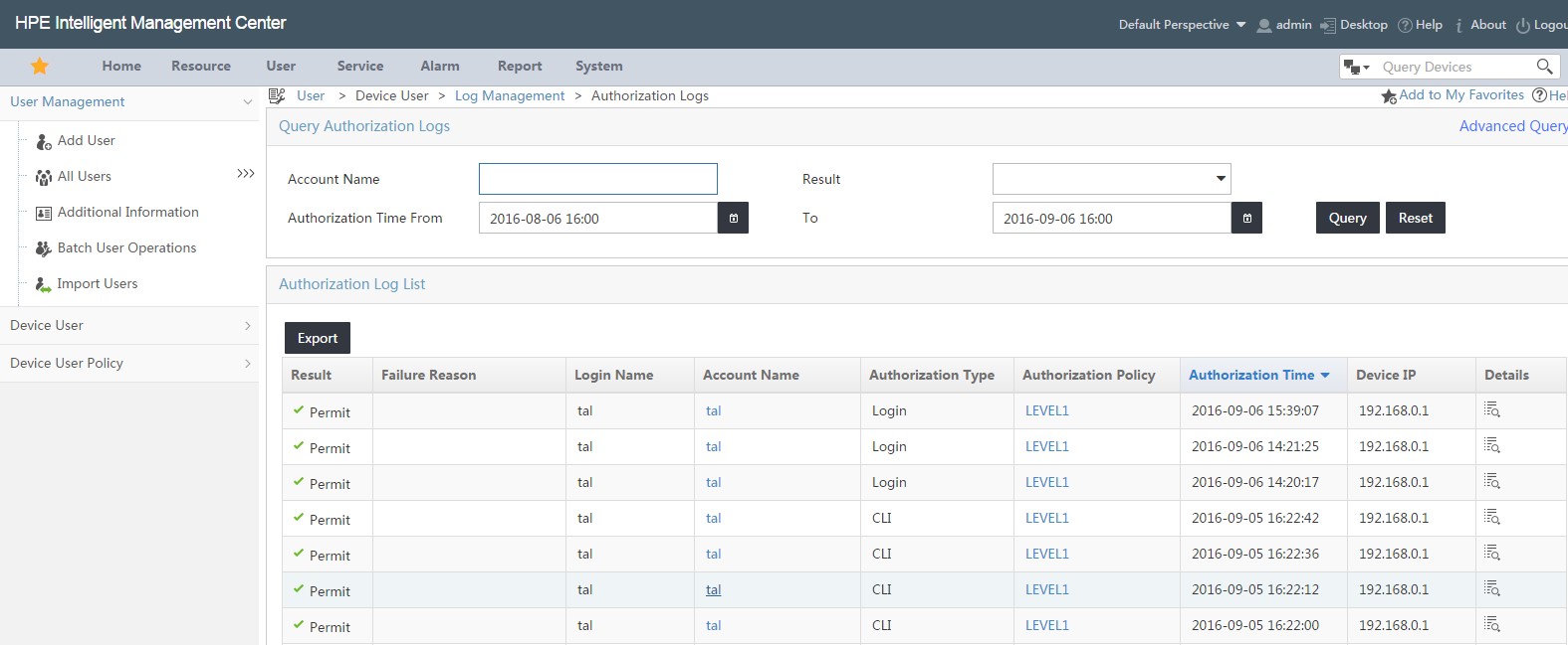
To view all authorization logs:
User -> Device User -> Log Management -> Authorization
Logs*
To view all audit logs:
User -> Device User -> Log Management -> Audit Logs*

*Note you can click on details for more verbose information
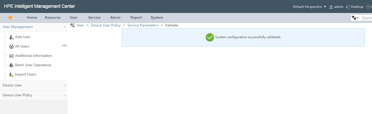
To validate system configuration:
User -> Device User -> Service Parameters -> Validate
To validate switch configuration:
Use the command: display hwtacacs <SCHEME_NAME>
Example:
|
[HP]display hwtacacs TEST
---------------------------------------------------------------------------
HWTACACS-server template name
: test
Primary-authentication-server
: 192.168.0.10:49
Primary-authorization-server
: 192.168.0.10:49
Primary-accounting-server
: 192.168.0.10:49
Secondary-authentication-server
: 0.0.0.0:0
Secondary-authorization-server
: 0.0.0.0:0
Secondary-accounting-server
: 0.0.0.0:0
Current-authentication-server
: 192.168.0.10:49
Current-authorization-server
: 192.168.0.10:49
Current-accounting-server
: 192.168.0.10:49
Nas-IP address
: 192.168.0.1
key authentication
: Qwer1234
key authorization
: Qwer1234
key accounting
: Qwer1234
Quiet-interval(min)
: 5
Realtime-accounting-interval(min) : 12
Response-timeout-interval(sec)
: 5
Acct-stop-PKT retransmit times
: 100
Username format
: without-domain
Data traffic-unit
: B
Packet traffic-unit
: one-packet
-------------------------------------------------------------------
|
