Here is the
following scenario:
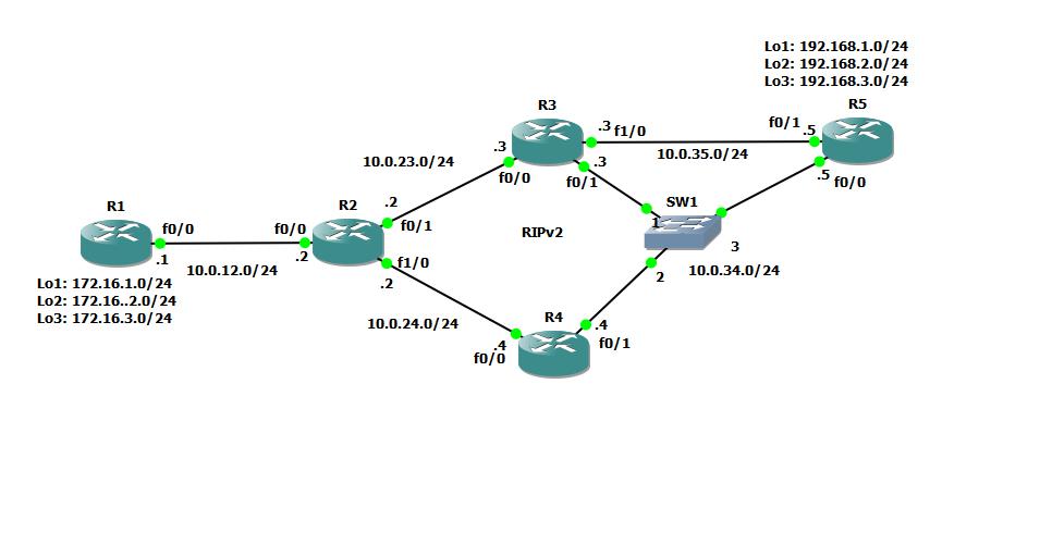
R1
configured with 3 networks:
Loopback 1 –
172.16.1.0/24
Loopback 2 –
172.16.2.0/24
Loopback 3 –
172.16.3.0/24
R5
configured with 3 networks:
Loopback 1 –
192.168.1.0/24
Loopback 2 –
192.168.2.0/24
Loopback 3 –
192.168.3.0/24
RIPv2 is
running on R2-R3-R4 and R5 on all interfaces and configured with only one path
(maximium-paths 1).
R1 is
configured with default route to R2 (10.0.12.2) while R2 is configured with
static routes to R1 networks (172.16.x.0/24) and redistribute them using redistribute
static on RIP.
So when
sending an ICMP, from R1 to R5, it will go through R2 and R4:
|
R1#traceroute 192.168.1.1
Type escape sequence to abort.
Tracing the route to 192.168.1.1
1 10.0.12.2 36 msec 48 msec 20 msec
2 10.0.24.4 56 msec 52 msec 28 msec
3 10.0.34.5 76 msec * 76 msec
|
Now let’s
assume that we want network 172.16.1.0 to reach R5 through R3, without modifying
anything in the RIP domain, for that purpose we will use policy routing on R2
as followed:
First we
will configure an access-list to match our criteria:
|
ip access-list standard
NET172-16-1-0
permit 172.16.1.0 0.0.0.255
|
Then we will
configure a route-map to do select match-set action:
|
route-map RM_NET1_R3_R5 permit 10
match ip address NET172-16-1-0
set ip next-hop 10.0.23.3
|
And apply
this route-map on the interface toward R1:
|
interface FastEthernet0/0
ip address 10.0.12.2 255.255.255.0
ip policy route-map RM_NET1_R3_R5
speed 100
full-duplex
|
Note that
unlike service-policies the ip policy doesn’t have direction, input or output,
it relays on the action taken in the route-map which depend on the ACL
configured.
The result:
|
R1#traceroute 192.168.1.1 source
172.16.1.1
Type escape sequence to abort.
Tracing the route to 192.168.1.1
1 10.0.12.2 48 msec 40 msec 20 msec
2 10.0.23.3 40 msec 36 msec 28 msec
3 10.0.34.5 116 msec * 60 msec
R1#traceroute 192.168.1.1 source
172.16.2.1
Type escape sequence to abort.
Tracing the route to 192.168.1.1
1 10.0.12.2 36 msec 44 msec 24 msec
2 10.0.24.4 48 msec 44 msec 20 msec
3 10.0.34.5 72 msec * 60 msec
|
While sending
an ICMP with 172.16.1.1 to R5 it will go through R3, all other networks will go
through R4
Reliable Policy-Based Routing
Now let’s
say that we want HTTP traffic (port 80) from R1 to R5 to go through R3 while
all other traffic from this network will go through R4
Now we will
configure extended ACL:
|
ip access-list extended
NET172-16-2-0
permit tcp 172.16.2.0 0.0.0.255 any eq www
|
Then we will
add to the route-map another match-set condition:
|
route-map RM_R1_TO_R5 permit 20
match ip address NET172-16-2-0
set ip next-hop 10.0.23.3
|
No need to
add the ip policy to the interface as it’s already configured
The result:
|
R1#traceroute 192.168.1.1 source
172.16.2.1
Type escape sequence to abort.
Tracing the route to 192.168.1.1
1 10.0.12.2 48 msec 36 msec 20 msec
2 10.0.24.4 32 msec 40 msec 40 msec
3 10.0.34.5 80 msec * 76 msec
|
While connecting
to 192.168.1.1 using telnet port 80:
<policy-route_01.img>
Next we will
add backup route to this policy by configuring default-route in case of R3
failure by adding the following lines into the route-map:
|
route-map RM_R1_TO_R5 permit 20
match ip address NET172-16-2-0
set ip next-hop 10.0.23.3
set ip default next-hop 10.0.24.4
set ip next-hop verify-availability
|
The command set ip default next-hop sets the next-hop
to 10.0.24.4 only if no route can be found first in the routing table.
The command set ip next-hop verify-availability check
and validate R3 reachability using CDP protocol, in case of failure to reach R3
normal routing decision will take place.
After disable
CDP run on R3, R2 sees only R4 on the CDP neighbors table:
|
R2#sh cdp neighbors
Capability Codes: R - Router, T -
Trans Bridge, B - Source Route Bridge
S - Switch, H - Host, I - IGMP, r
- Repeater
Device ID Local Intrfce Holdtme Capability Platform
Port ID
R4 Fas 1/0 174 R S I 2691 Fas 0/0
|
Now trying
to telnet 192.168.1.1 with source 172.16.2.1 while debugging the policy route
with the command debug ip policy on
R2:
|
*Mar 1 09:13:53.401: IP:
s=172.16.2.1 (FastEthernet0/0), d=192.168.1.1, len 28, FIB policy
rejected(explicit route) - normal forwarding
|
We can see that
ip policy route is rejected and normal route is being used.
In the third
scenario we will use IP-SLA and track object as another option for reliable
policy-based routing, in this way we can track a non-directly connected hosts.
In the
following example we will track interface f0/1 on R5
First configure
an IP-SLA:
|
ip sla monitor 1
type pathEcho protocol ipIcmpEcho 10.0.35.5
frequency 5
ip sla monitor schedule 1 life
forever start-time now
!
track 1 rtr1
|
Take note
that network 10.0.35.0/24 is filtered from R2 routing table, route to this
prefix is based on static route else R2 could find a way through R4 or R3
switch interface.
Then the configuration
of the new ACL and route-map:
|
ip access-list standard
NET172-16-3-0
permit 172.16.3.0 0.0.0.255
!
route-map RM_R1_TO_R5 permit 30
match ip address NET172-16-3-0
set ip next-hop verify-availability 10.0.23.3 1 track 1
set ip default next-hop 10.0.23.4
|
Verification:
|
R1#traceroute 192.168.1.1 source 172.16.3.1
Type escape sequence to abort.
Tracing the route to 192.168.1.1
1 10.0.12.2 40 msec 36 msec
16 msec
2 10.0.24.4 48 msec 36 msec
24 msec
3 10.0.34.5 72 msec * 104 msec
|
After shutting
down interface f0/1 on R5:
|
R1#traceroute 192.168.1.1 source 172.16.3.1
Type escape sequence to abort.
Tracing the route to 192.168.1.1
1 10.0.12.2 40 msec 52 msec
16 msec
2 10.0.23.3 52 msec 44 msec
20 msec
3 10.0.35.5 72 msec * 116 msec
|
IP-SLA can
help us track and measure different parameters on our network and to configure
conditional action based on the results but currently it’s out of the scope of
this post.
Take note
that starting from IOS 12.0 PBR is supported in the Cisco
Express Forwarding (CEF) switching path. CEF-switched PBR has better
performance and, therefore, is the optimal way to perform PBR on a router.
More information can be found in the following link:
http://www.cisco.com/en/US/docs/ios/12_0/qos/configuration/guide/qcpolicy.html#wp5666

